Description
Feature
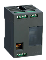
Single-circuit AC power monitoring unit F-MPC04E (CRS-485Type/SD card type) series
Internal panel mountable devices for single-circuit F-MPC power monitoring unit.
RS-485 interface is default.
Even more affordable price range with selected functions from F-MPC04S.
Reduce the dimensions to half, the mass to 1/3 of that of the F-MPC04S.
Reduce 30% of the power consumption of that of the F-MPC04S.
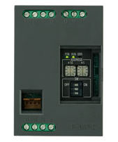
Simple configuration setting by rotary and dip switches
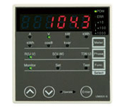
Capable of displaying data with the optional indicator
Types and ratings
General specifications
Item | Specifications | ||
---|---|---|---|
Ratings | Voltage | AC100~240V(Allowable operational voltage range: AC85~264V) | |
[measuring and control power supply share input terminals control power supply is among U-V terminals] | |||
Frequency | 50/60Hz(Allowable range: 47.5~63Hz) | ||
Current (CT primary / secondary) |
AC5A/7.34mA、AC50A/73.4mA、AC100A/33.3mA、 AC200A/66.7mA、AC400A/133.3mA、AC800A/133.3mA |
||
Power supply | Burden VA Inrush current |
6VA 30A、3ms(240V) 15A、3ms(100V) |
|
Insulation resistance | Between electric circuits and ground(Housing: DIN rail) | 10MΩmin. | |
Between I/O circuits and ground | 10MΩmin. | ||
Electric circuits and I/O circuits | 5MΩmin. | ||
Vibration resistance | 10 to 58Hz: single amplitude of 0.075mm, 58 to 150Hz, constant acceleration of 10m/s2 8minutes ×10cycles in each of X, Y, and Z directions with retainers |
||
Shock resistance | Half-sine 294m/s2, 11ms, 3 times in each of X, Y, and Z directions (with retainers) | ||
Withstand voltage | Between terminals and ground(Housing: DIN rail) AC2,000V | 1min. | |
Electric circuits and I/O circuits AC2,000V | 1min. | ||
Noise immunity | Damped oscillatory wave 1~1.5MHz Peak voltage damped oscillatory wave form(2s) of 2.5~3kV | ||
Judgment criterion B | Square wave 1ns×1μs 1.5kV of square wave noise for 10 min continuously. | ||
Radiation field 20V/m(*1) | |||
Electrostatic discharge Aerial discharge: 8kV, Contact discharge(Housing): 4kV | |||
Burst Control power supply: 2kV, CT input: (clamping) 2kV, I/O(clamping): 1kV |
|||
Overload resistance | CT circuits | 110% of maximum setting value (125% of rated current), 2 hours | |
VT circuits | 110% of max. setting value, 2 hours | ||
Operating ambient temperature | -10~55℃ | ||
Storage temperature | -20~70℃ | ||
Humidity | 20~90%RH(No condensation) | ||
Atmosphere | No corrosive gas and no heavy dirt and dust | ||
Permissible momentary power failure | 20ms(Connection and measurement are interrupted) | ||
Mass | [Measuring unit] Aprox.120g(without CT) | ||
[Display] Aprox.70g(without connection cable) |
(*1)Under strong radiation circumstance, power monitoring unit may temporary stop operation.
Measurement specifications
Item | Measuring range | Accuracy | |
---|---|---|---|
Voltage | 3phase(line-voltage)(*2) (Vuv,Vvw,Vwu) |
85~264V | Vuv,Vvw: ±1.0%FS Vwu: ±2.5%FS |
Current | 3 phase current(*2) (Ir,Is,It) |
0.4~125% of rated current (50A CT:0.4~100%、100A CT:0.4~120%) |
Ir,It: ±1.0%FS Is: ±2.5%FS |
Active power (*3) |
Inverse electric power flow is minus | Depends on CT/VT measuring range (current×voltage×√3) |
±1.0%FS |
Reactive power (*3) |
Active electric energy for forward or reverse flow | Display:6digits | Equivalent to ordinary class specified in JIS |
F-MPC-Net protocol:4 digits | 2.0% at power factor of 1.0 between 5 to 120% of rated current |
||
MODBUS protocol:9digits | 2.5% at power factor of 0.5 between 10 to 120% | ||
Power factor | (Reactive volt-ampere meter method) | 0~±1.000 | ±3.0%FS (The “90°” phase angle conversion) |
(*1)Accuracy performance excludes the errors in the external CT and VT.
(*2) Automatically judge whether 3-phase 3-wire system, single-phase 3-wire, or single-phase 2-wire for measurement. In case of single-phase 2-wire, Vvw, Vwu, Is, It will be zero.
(*3) Active power, reactive power and active electric energy are measured among the ranges of voltage 85-264V and current 0.4-125%.
(2)Measurement in a fixed-duration
Item | Display | Network | Accuracy | Memo | |
---|---|---|---|---|---|
Voltage | Fixed-term max. voltage (Vuv,Vvw) Fixed-term average voltage (Vuv,Vvw) Fixed-term min. voltage (Vuv,Vvw) |
× | ○ | ±2.5%FS (without VT error) |
The maximum/minimum values are those of RMS values within a cycle at commercial frequency. During a term (1 min.), holds the maximum/average/minimum values from a previous term. |
Current | Fixed-term max. current(Ir,It) Fixed-term average current(Ir,It) Fixed-term min. current(Ir,It) |
× | ○ | ±2.5%FS (without CT error) |
(*1)Respond value by minute via network. (Not in a display)
Communications specifications
Item | Specifications | ||
---|---|---|---|
F-MPC-Net | MODBUS/RTU | ||
Standard | EIA-485 | ||
Transmission method | Half duplex, 2-wire | ||
Data exchange method | 1:N(Power monitoring unit) polling/selecting | ||
Synch system | Start-stop synchronization | ||
Transmission distance | 1,000m(total length) | ||
Number of stations | 64 max (*1) per system(including master) | ||
Transmission speed | 4,800/9,600/19,200/38,400 bps (selectable) | ||
Address setting | 1~99(*2)(MODBUS/RTU protocol 1~99) | ||
Connection method | Terminal block | ||
RS-485 terminal names | DXA、DXB | Connect DXA as D1(+) and DXB as D0(-). | |
Transmitted characters | ASCII | Binary | |
Data format | Start bits | 1 bit (fixed) | 1 bit (fixed) |
Data length | 7 or 8 bits (selectable) | 8 bit (fixed) | |
Parity bit | None, even, or odd (selectable) | None, even, or odd (selectable) | |
Stop bits | 1 bit(fixed) | No parity: 2 bits (fixed) Others: 1 bit (fixed) |
|
BCC | Even vertical parity | CRC-16 |
Factory default: F-MPC-Net protocols, transmission speed at 19,200bps, data length: 7bit,
(To modify the factory setting, the optional indicator [Type: UM05X-S] is required.)
(*1)When a device with 32 stations is connected, its connection is counted as 2 devices, and the maximum number of connectable stations will decrease.
(*2)Addresses are set with a rotary switch.
In either MODBUS or RTU, please set the monitoring unit address within the range of 1-99.
If you set the address at “00”, the network will be invalid.